After presenting you the concept of our MiniX ( you will find here a link to download the plans free of charge ), now let's get down to business and construction. Let's open a shipyard here!
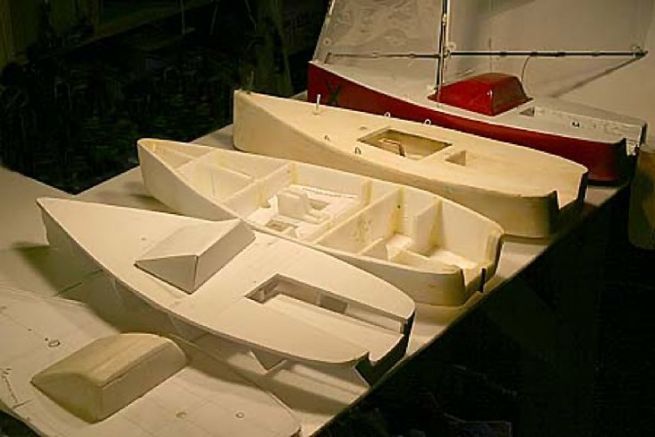
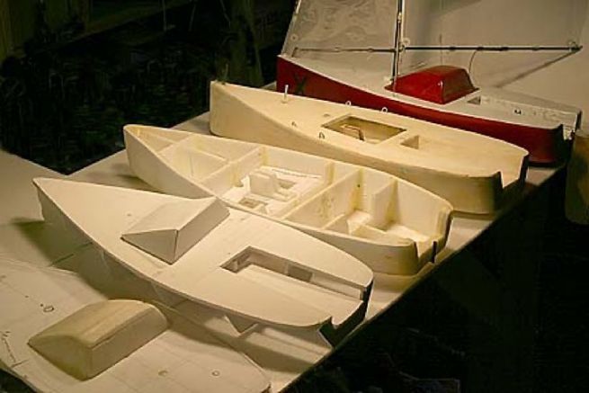
We offer you the fruit of our reflections and a quick follow-up of the realization of our MiniX. These are our ideas and solutions, but there are undoubtedly others. Don't think that everything was solved at first glance! Here are a few hull tests before arriving at the final solution. Behind these skeletons, there are a few hours of bubbling brains.
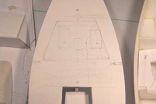
Here, a small example of cogitation to imagine the functioning of the two servo arms. Will there be enough room to house all the mechanisms?
Cutting of the structure
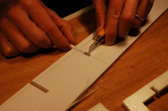
- Print the plans in A4 format from the PDF file.
- Tape together the sheets to be connected (you have markings on the overlapping planes).
- Glue the sheets with a repositionable spray glue (type 3M) on the 6 mm Depron.
- Cut with the cutter on the lines.
- Print (in duplicate), glue and cut out the two combs that are used to guide the squaring of the couples during gluing.
Gluing of couples
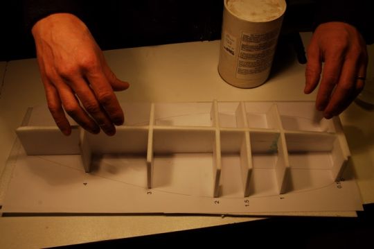
For gluing, we use epoxy resin lightly filled with silica to thicken it.
- Stick the couples on the central ridge.
- Make sure that the assembly is square by placing the skeleton above the plane. Make sure that each pair is square and that the central edge is not warped.
Gluing of top edges
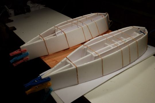
- Make a blank mount to visualize the pressures to be applied.
- The most delicate part is at the back where the Depron is on the verge of breaking. Take it easy. To limit the risk, you can heat the Depron with a hair dryer.
- A piece of string keeps the pressure on the back.
- Beware, under pressure the structure tends to rise. Watch its position carefully.
- Prevent the elastic bands from marking the planking too much by inserting protective wedges (from Depron Falls).
Gluing of the bottom planking
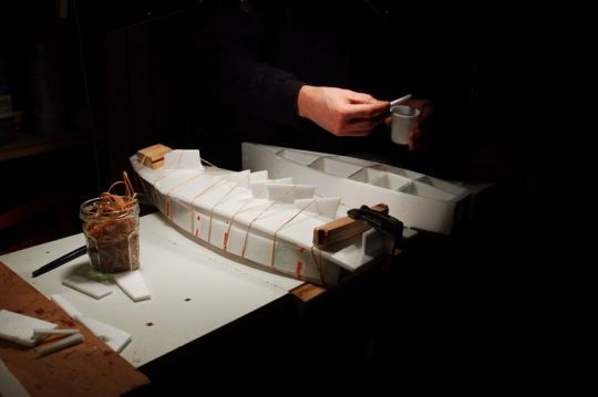
- Like the previous ones, the lower borders are also made of a 8 cm piece of Depron.
- To avoid marking the first planking too much with the rubber bands, it is protected by a Depron fall.
- The joint between the two planks must be ideally placed in the centre of the boat. To ensure a perfect connection between the two, you can angle the joint slightly using a sanding block and fine sandpaper.
Exterior stratification
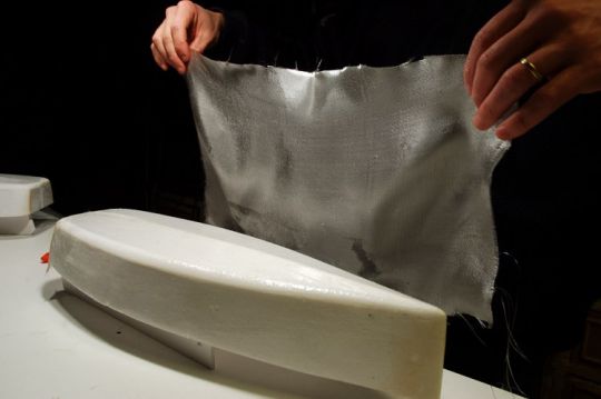
- The shell is covered with a layer of 86 g/m² glass cloth and a surface layer of 48 g/m² glass cloth. The second layer is placed at 45° to the first to distribute the stress on the fibres.
- Ideally, the same weight of fabric and resin should be used (here 40 g). In reality, we consumed 10 g more resin for "touch-ups".
- An 86 g/m² fabric is placed on the bow and another identical one on the transom.
- To facilitate the installation of the fabrics, the shell is installed on the combs already in use.
- Beware of the bubbles that can form as well as all the dirt that inexorably forms a visible bump in the finish.
- Excess fabric is cut off with scissors once the resin is dry.
Interior Stratification
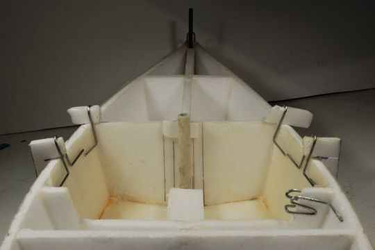
- It is necessary to hollow out the useless parts: the central bulkhead in the 2 compartments which will receive the electronics as well as the rear part to be able to install the cockpit.
- With fabric, we reinforce the centre of the boat which will support all the efforts: mast, shrouds and keel.
We use glass cloth:
- 86 g/m² for the bottom that rises to the edges.
- 86 g/m² that revolves around all vertical partitions.
- 48 g/m² to double the first lamination.
Construction of the mast
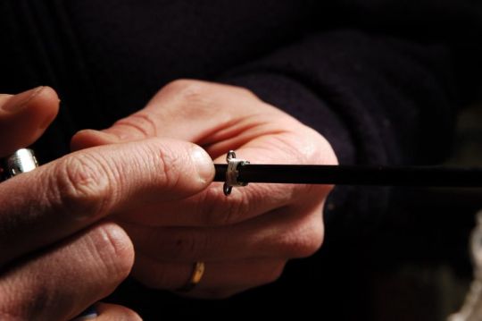
The metal anchor points are fixed to the mast with a binding made with sailing wire and then covered with resin. We used 1 mm piano wire, twisted as we wished, to make the anchoring points. The mast is a 6 mm carbon tube bought in the kite department of a sport shop.
We'll have to fix:
- The gooseneck which also serves as an anchor point for the vang.
- The jib furling system to which the two shrouds and the forestay return.
- The masthead for the main halyard. We have also planned for a possible backstay so as not to be restricted for future modifications (but after a few sailings, it seems that we will never use them...).
Chainplates and mast step
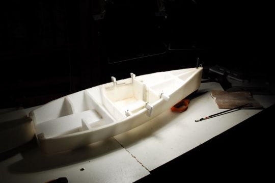
You will notice that we have positioned four shroud locks, where two would have been sufficient. The furthest ones are used to tension the forestay, but we were afraid that the shrouds would interfere with the opening of the mainsail downwind, so we placed two more further forward. In use, the backward position doesn't interfere, we always use the rear chainplates. Note that the mast's 6 mm carbon tube, which is 10 cm long and is embedded in the hull, is enough to make the mast without shrouds. But in this case the forestay is too slack, hence the presence of shrouds (not to mention the unsightliness of a mast without shrouds...).
- The mast step is a tube that we made ourselves by laminating over the mast tube. In order to be able to remove it from the mould, we covered it with cling film. There are also 8 mm carbon tubes with 6 mm inside.
- The chainpads are made by twisting 1 mm piano wire.
- Their gluing is simple if you are careful. Avoid large patties that will be impossible to sand afterwards.
- You're going to need a good eye to get the mast upright..
Jib boom
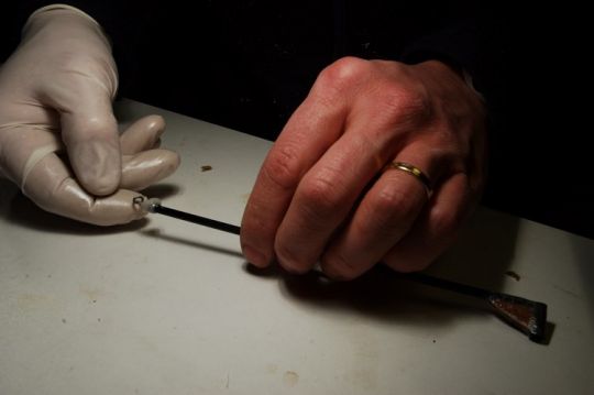
- The jib boom must not rise towards the sky when it is shocked, otherwise its sail will open at the top and lose all its power downwind. Unlike a mainsail, it is not possible to install a vang. We have therefore solved this problem by installing a vertical rotation axis that blocks the boom upwards.
- The rotation axis (fixed in the hull) is cut in a 4 mm carbon tube (like the boom) while the pivot will be the same 6 mm carbon tube.
- The two parts are assembled with filled resin and reinforced with a 3mm plywood triangle (or whatever you have).
- The axis of rotation will be glued into the bow, itself well reinforced to support the effort.
- It is simpler to be in pairs when drilling to ensure proper alignment (in both planes) so that the axis is vertical.
Keel well and servo support
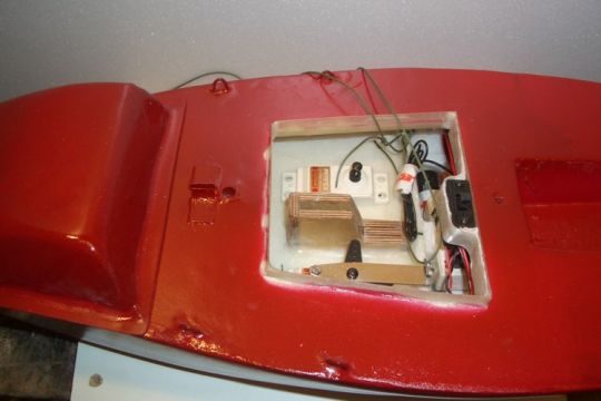
The keel well is made of plywood. The keel penetrates inside and is held in place with a bolt locking system. The keel well must be well adjusted to avoid play in the keel. The conical shape at the back makes it possible to lock the keel well.
All the mechanics (servos) are distributed on each side of the keel. We have fixed a horizontal support made with a Depron sandwich.
Bridge bonding and coating
The deck is glued to the top of the couples and covered with a glass cloth that goes down slightly on the planks. With a fine coating, a perfect finish is obtained.
Rouf
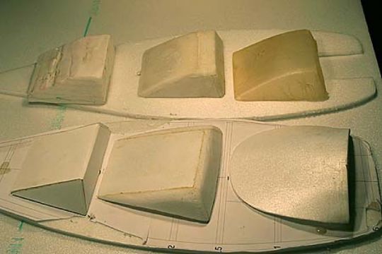
The design of the deckhouse was the result of several modelings. But after a few tries, we made a polystyrene mould. The deckhouse is held on the deck only by angles all around the opening, which also provides a semblance of watertightness.
The angles are made of composite (resin + fabric) on a square wood covered with kitchen paper. We used about ten 48g fabrics to make a 0.5 mm thick piece.
Painting
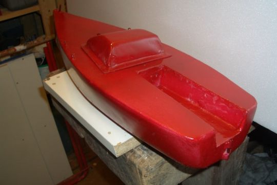
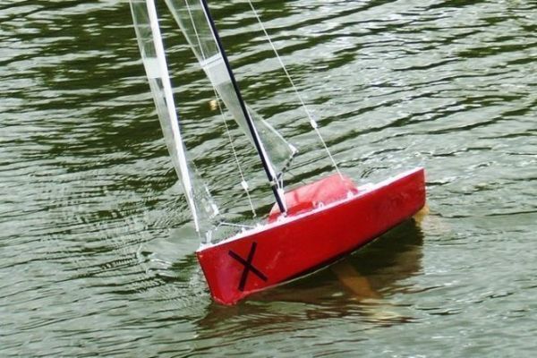
It's not our forte, but we've still given our MiniX a little sailboat look.
Ballast moulding
The ballast is made of lead, to realize it, we made a wax mother piece (a candle that we brought to the desired shape. Then plaster casting in 2 half-moulds before casting lead definitively. In each ballast, we have "celé" screws which come to stick in the keel veil.
Keel
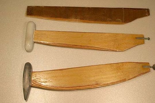
The keel is made of plywood. The bulb is glued at the bottom.
We groped our way through before finding the right compromise for the ballast position. Three versions of the keel: the last one (bottom) is starting to meet the specifications, and in profile, we can see that the ballast is set back from the keel axis. We came to this conclusion after testing other keels. The junction with the hull works. Well wedged in the keel well, the keel doesn't move a hair.
Safran
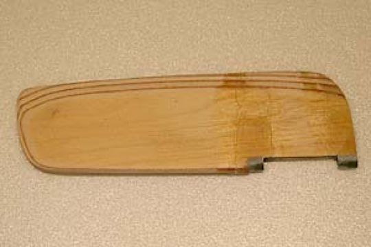
The rudder blade (see drawing for shape) is cut from 4 mm plywood.
It is then refined at the back and rounded at the front.
Purists will say that the two sides should not be symmetrical so that the water streams do not come off. Moreover, the trailing edge must not be pointed, but on the contrary at right angles, always for water threads. But it is difficult to do this on such a small scale.
In the end, we applied a few coats of varnish to the rudder to ensure a semblance of a watertight barrier.
Sails
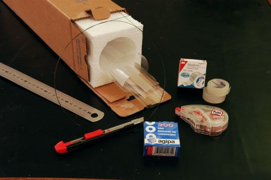
The sails are built with widths glued with Blenderm (surgical tape that you can buy in pharmacies). The sail "fabric" is simply film that the florist uses to wrap his bouquets. It's incredibly strong and won't warp.
Fittings
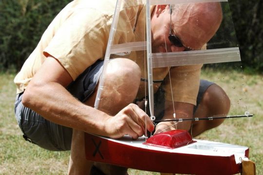
- For the sails to transmit all their power, you must look for rigid ropes (not elastic). We went to a kite shop to find 0.5 mm bitch.
- Customised" fishing clamps ensure the connection with the chainplates and allow the mast to be removed.
- Without the possibility of reducing the mainsail (we have no reefing), the only solution left is to flatten the sail as much as possible to limit its power. So we have a trim and adjustable halyard tension. The vang also allows us to open the sail downwind.
- Pieces of transparent tube (from an aquarium), are forced onto the carbon booms. They are the ones that block the manoeuvres and allow the tension adjustments.
- Tensioners are plastic parts with three holes.
